Draw Circles at Selected Point With Specific Radius Tableayu
Here is How to create circles and arcs objects in AutoCAD
Circumvolve C (allonym)
D r a due west + Circle + [Option]
Draw ![]()
You can use the Circle command and select control line options manually to create CIRCLEs using different methods
- or yous can pre-select the method that you want to utilise from the
- AutoCAD automatically supplies appropriate responses to prompts when you lot use a pulldown menu to invoke Circle.
- the aforementioned Circumvolve command is used for all pulldown carte options.
Draw + Circle cascading pulldown bill of fare.
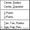
For example, y'all could option Draw + Circle + Center,Diameter to create a Circle by suppling a center point and a diameter
- or you could use Circle manually and select options for diverse prompts to achieve the same end results (encounter dialogue beneath).
Command: CIRCLE↵
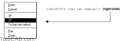
Specify center point for circle or [3P/2P/Ttr (tan tan radius)]: 3,3 ↵
Specify radius of circle or [Diameter]: D ↵
Specify diameter of circle: 2↵
Command:
You tin right-click in the drawing area to invoke a shortcut bill of fare to select a command prompt listed inside [foursquare brackets]
The default method is Center,Radius when y'all use Circle manually (and when you invoke it past picking the Circle toolbar button)
- but y'all can select command line options to use whatever of the other methods if you wish.
Cull the method that is well-nigh convenient for the task at hand.
- for instance, if you know the radius and then it is like shooting fish in a barrel to use Eye,Radius direct.
- whereas, if yous know the diameter it may be easier to utilize Center,Diameter (avert miscalculating ii*Radius in your head).
When thee Radius,Diameter or Center are not known:
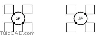
You tin can use 3P (3 Points) to create a Circle that must laissez passer through 3 specific points when you lot exercise not know the required radius
- or employ 2P (2 Points) to draw a CIRCLE such that the diameter is the altitude between these two points.
Employ Ttr (Tan,Tan,Radius) to brand a Circle with a specific radius that is tangent to ii other objects
- or employ Tan,Tan,Tan (pulldown only) to create a Circle with an unkown radius such that information technology is tangent to three other objects.

Y'all can utilise the Arc command (like Circle) and select command line options manually to create ARCs using unlike methods
- or you tin pre-select the method that you desire to employ from the Describe + Arc cascading pulldown menu.
- AutoCAD automatically supplies appropriate responses to prompts when y'all use a pulldown carte du jour to invoke Arc.
- the same Arc command is used for all pulldown card options.
Draw + Arc +

- As with the Circle command, you lot can invoke the Arc command manually and apply the same methods listed in the pulldown menu
- but if yous utilize a pulldown menu to select a method the required responses to prompts are supplied by AutoCAD automatically.
Yous must supply points in sequence such that the ARC is created in a counter-clockwise direction (except for the three Points choice)
- otherwise yous could create an ARC that would form a consummate CIRCLE if you added it to the desired ARC.

You lot can utilise Circle to create a CIRCLE object and and so Trim the CIRCLE to create the desired ARC object instead of using Arc
- and you lot tin use the Fillet command to add blended ARC objects where LINEs or ARCs run into in corners.
- you volition be learning more about the Trim & Fillet commands in the CAD Construction Techniques document later in this course.
The method you choose to create an ARC will depend on the required ARC and the points you tin hands snap to.
- if your drawings require many ARCs you lot might want to get familiar with most (or all) of the different methods
- but if you do not require many ARCs in your drawings you lot tin can get familiar with a few bones methods instead.
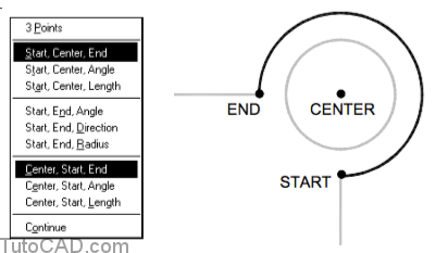
Many ARCs can be created using a Center, First & End points and there are 2 pulldown carte du jour options to create ARCs with these points.
- you would use either of these options when you can hands snap to these iii points to specify the desired ARC.
- for example, the first & end of the desired ARC might join existing LINEs & take the same center equally an existing Circle.
Control: _arc Specify get-go point of arc or [CEnter]: END ↵
of (option first indicate using ENDPOINT osnap on existing LINE)
Specify second point of arc or [Heart/Finish]: _c Specify center indicate of arc: CEN ↵
of (pick center indicate using CENTER osnap on existing Circumvolve)
Specify end signal of arc or [Bending/chord Length]: Cease ↵
of (pick finish point using ENDPOINT osnap on existing LINE)
Command:
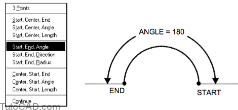
Iii Arc pulldown bill of fare options use Bending as one of the parameters and this is the included angle equally shown below.

Use start & end points and the required included bending if you lot exercise not know the required center bespeak.
Employ get-go and center points with the required included angle if you practise not know the required terminate point.

Two Arc pulldown card options use Length every bit one of the parameters and this is the string length as shown beneath.

You tin apply the Start,End,Direction method when the initial tangent direction is more than of import than a radius or a center bespeak.
- for instance, yous could use this method to ensure that the new ARC is tangent to an existing LINE object.
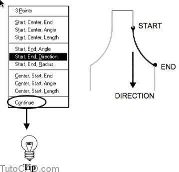
When you lot use the Go along selection for Arc the next ARC volition automatically begin where your last ARC (or LINE) concluded
- and the new ARC is also forced to be tangent to the concluding ARC (or LINE) object.
- you lot tin can use other commands (in the same drawing session) after you create your final ARC (or LINE) & nonetheless use Continue.
- two (of the required three components) are already known when you use Continue so you are prompted Only for an terminate signal.
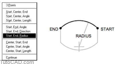
Use the Start,End,Radius method when these three parameters are known and AutoCAD automatically finds the required middle bespeak.
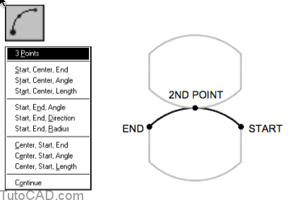
3 Points is the default method when you invoke Arc manually and practice not select whatsoever command line options.
- this is also the default method when you invoke Arc past picking the Arc toolbar button.
- this is the just Arc method in which you can specify points in either a clockwise or counter-clockwise management.
PRACTICE: MAKING CIRCLES AND ARCS TUTORIAL IN AUTOCAD
1) Shut the drawing from the previous practice (if it is open up).
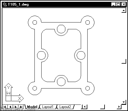
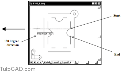
2) Open the T105_1.dwg drawing in your personal folder.
Your drawing should wait like this gasket AFTER you lot complete the next exercise.
Yous will add the ARCs and CIRCLEs shown using existing LINEs to snap to.
3) Pick Tools + Run Script. Select your personal folder to Look in and select T105.scr as the script File name. And so pick the Open push to run this script. (This script will set your drafting settings to friction match the beliefs described in this exercise).
4) Left-click on the POLAR and OSNAP condition bar buttons to turn these drafting tools On.
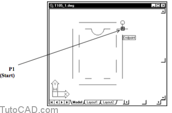
5) Selection Depict + Arc + Outset,Center,Terminate. Movement your crosshairs to the meridian of the LINE shown near P1 to invoke an Endpoint osnap for the start of the new ARC. Left-click to use that point and continue with the next prompt.
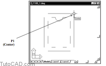
half dozen) Move your crosshairs to the CIRCLE near P1 to invoke a Centre osnap when AutoCAD prompts for the ARC center point. Left-click to utilise this betoken and continue.
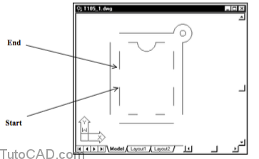
vii) Finally, motion your crosshairs to the stop of the LINE near P2 to invoke an Endpoint osnap and left-click to supply this point as the cease of the ARC.

eight) Examine your control line history.
Command: _arc Specify outset point of arc or [Middle]: (commencement)
Specify second point of arc or [Heart/Terminate]: _c Specify center betoken of arc: (center)
Specify end point of arc or [Angle/chord Length]: (end)
Command:
AutoCAD automatically supplied _c to apply the adjacent bespeak supplied as the center of the ARC (instead of the default second betoken).
9) Pick Draw + Arc + Start,Finish,Angle. Use Endpoint osnaps for the Start and End points & enter 180 as the angle.
10) Pick Describe + Arc + Showtime,End,Direction. Use Endpoint osnaps for the Start and End points and hold your crosshairs to the left and then the Polar tooltip is 180 degrees when prompted for the direction. Left-click to complete this ARC.
Examine the three new ARCs you have created so far and trace these ARCs (in your mind) from the start point to the terminate point.
- these ARCs are created in a counter-clockwise management.
- if your ARCs do not look like those in the analogy you may have picked your points in a clockwise direction instead.xi) Pick Draw + Circle + Center,Bore. Employ a Heart osnap on the existing ARC near P1 every bit the center point for the new Circle and type 0.125 as the diameter.

MORE PRACTICE
12) Add the remaining ARCs & CIRCLEs on your own.


13) Save changes then Shut the T05_1.dwg cartoon.
14) Pick File + New and select Kickoff from Scratch. Use English default settings and pick OK to go on.
15) Pick File + Salve and apply Conveyor.dwg every bit the File proper noun. Salve this file in your personal folder.
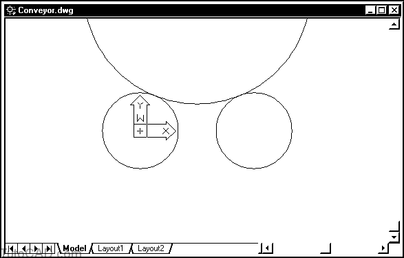
16) Pick Describe + Circle + Eye,Diameter. Enter 0,0 as the center of the Circumvolve and enter 12 as the bore.
17) Pick Draw + Circle + Center,Bore. Enter 18,0 as the center of the CIRCLE and enter 12 as the diameter.
xviii) Pick View + Zoom + Extents.
19) Selection View + Zoom + Out.
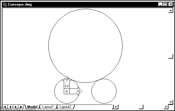
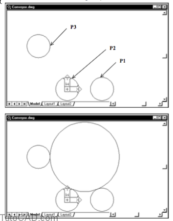
20) Selection Draw + Circle + Tan,Tan,Radius. Selection the first Circumvolve near P1 then choice the second Circle near P2 when prompted for tangent points. Then enter eighteen when prompted for a radius.
21) Pick View + Zoom + Extents.
22) Pick Draw + Circumvolve + 2 Points. When prompted to Specify first cease point of circle's diameter printing and agree the <Shift> key and right-click in the drawing expanse to invoke a shortcut carte du jour. Then select Quadrant as the osnap override and left-click near P1 beneath.
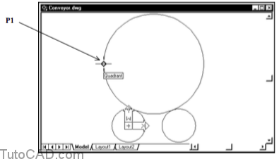
23) When prompted to Specify second end point of circumvolve'south diameter enter @12<180.
24) Choice Tools + Inquiry + Distance and use Center osnaps for the CIRCLEs near P2 and P3 to find the distance between the conveyer and the shock cushion.

Command: '_dist Specify first bespeak: (use Center osnap on Circumvolve near P2)
Specify second point: (use Center osnap on CIRCLE near P3)
Distance = 39.7995, Bending in XY Aeroplane = 146, Angle from XY Plane = 0
Delta Ten = -33.0000, Delta Y = 22.2486, Delta Z = 0.0000
Command:
Suppose you knew where the daze absorber was located but you lot were looking for the diameter of the larger Circumvolve instead.
- in the side by side few steps you will re-create the large CIRCLE past creating information technology tangent to the iii other smaller CIRCLEs.
25) Select the large Circle (when no command is running) and printing the Delete fundamental to Erase it.
26) Pick Draw + Circle + Tan,Tan,Tan. Click on CIRCLEs about P1, P2 and P3 as the tangent points for the new CIRCLE.
27) Selection Tools + Inquiry + List & select the large CIRCLE. Press <enter> & read the report (the radius should be 18) And so printing F2 to return to the drawing window.
28) Pick File + Save to update your changes to Conveyor.dwg.
Source: https://www.tutorial-autocad.com/creating-circles-arcs
0 Response to "Draw Circles at Selected Point With Specific Radius Tableayu"
Post a Comment